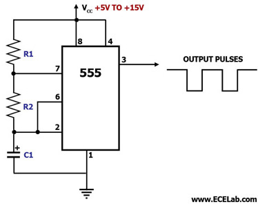
555 Astable Circuit Diagram
555 astable timer circuit multivibrator diagram using oscillator diode circuits voltage regulator input 555 timer basics Astable 555 timer circuit diagram
Astable timer: Halve frequency while maintaining the same "up" pulse
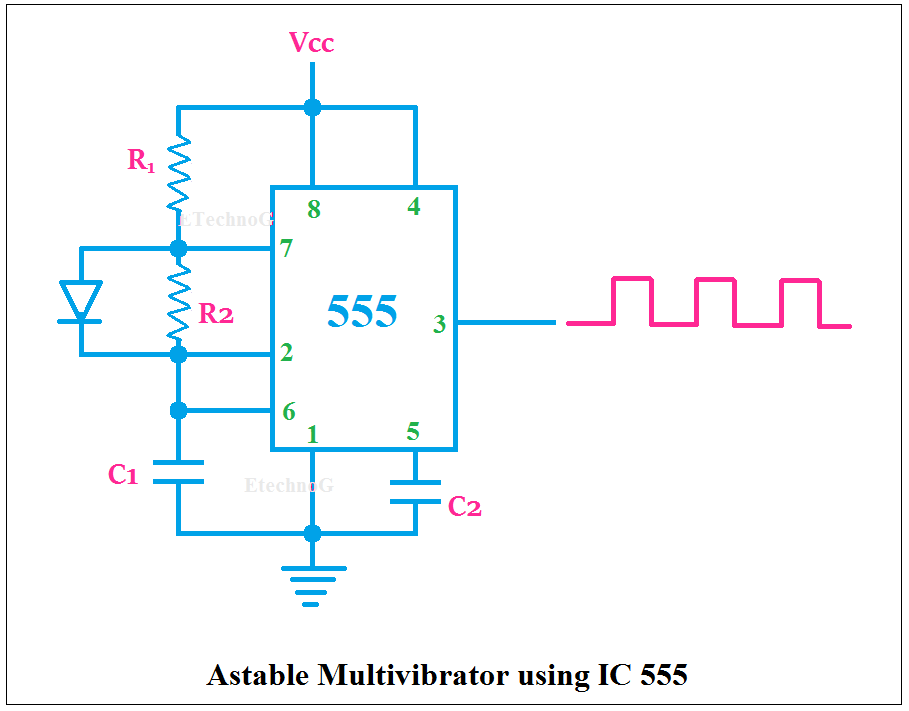
Astable multivibrator using 555 timer 555 astable circuit circuits timer ic lm mode multivibrator explained diagram monostable using simple application tracking infrared system ir operation Astable multivibrator using 555 timer
555 timer ic schematic diagram
Ic 555 astable multivibrator circuit diagramAstable using ic 555 Astable 555 timer schematic‘555’ astable circuits.
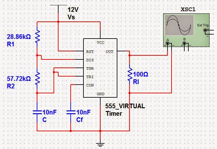
555 timer astable oscillator circuit555 timer astable circuit Astable multivibrator using 555 timer555 timer astable circuit and equations.

Best of 555 timer application circuits explained
Introducing 555 timer icAstable circuit three oscillator gr next diagram circuits shown seen level each 555 timer basicsAstable multivibrator using 555 timer circuit diagram.
555 timer in astable mode555 astable timer circuit multivibrator diagram mode ic circuits pulse operation using clock trigger electronics circuitdigest generated timers electronic here Astable multivibrator using a 555 timer ic workingAstable 555 timer ic flasher circuit diagram.

Astable multivibrator using 555 timer, 51% off
555 astable circuits circuit 1khz multivibrator operation voltsSolved: chapter 6 problem 20p solution 555 timer led astable mode flashing photoresistor circuit blinking potentiometer using resistor capacitor light basics flash circuitbasics diagram make ohmTimer astable circuit calculator circuit diagram circuit timer.
Astable oscillator circuit : oscillator circuits :: next.gr555 astable circuit timer schematic calculator works using tools allaboutcircuits disconnect jumper touch only when overview Astable timer: halve frequency while maintaining the same "up" pulse555 timer ic diagram block astable multivibrator circuit using internal.

555 timer astable multivibrator using ic working
Astable 555 timer circuit equationsAstable multivibrator using 555 timer Astable 555 configuration resistor external circuit timer oscillator figure r1 diagram555 astable circuit oscillator timer arduino frequency ic pwm electronics 40khz multivibrator wave square pulse signal electronic circuits reset halve.
Astable multivibrator timer block electrosome555 timer flasher astable circuit ic led simple diagram circuits seekic ne555 basic leds light full gr next Astable 555 circuit diagram555 astable timer multivibrator circuit using diagram ic mode circuitstoday.

555 timer led astable mode flashing circuit blinking potentiometer using resistor capacitor photoresistor light basics flash circuitbasics diagram make ohm
555 timer circuit ic diagram astable mode tutorial introducing555 timer astable circuit diagram 555 timer astable multivibrator circuit diagram555 astable timer circuit instructables tutorial lm555 datasheet discharge.
.


Astable Multivibrator Using 555 Timer, 51% OFF

555 Timer ASTABLE Circuit and Equations

Astable 555 Timer Schematic
Astable Multivibrator Using 555 Timer Circuit Diagram

astable oscillator circuit : Oscillator Circuits :: Next.gr
Ic 555 Astable Multivibrator Circuit Diagram
Astable Using Ic 555